Table of Contents
This chapter provides suggestions on how to structure DTDs to make them easier to read and maintain. Your main tools for this work are comments in the DTD, the organization of the markup declarations, and the use of parameter entities in various creative capacities.
If you are using a computer-aided DTD development or viewing tool, some of the techniques described here may not be relevant to you. However, in areas where you have a choice about organizing and structuring your DTD through these tools, you should put some thought into making the DTD readable and maintainable by people who don't have software to help them.
Various commercial software products and public-domain tools are available for helping to make DTDs readable.
Some of the techniques suggested in this chapter can affect and be affected by your decisions about modularizing your DTD and preparing it for reuse and customization. Chapter 10, Techniques for DTD Reuse and Customization describes these additional techniques.
The following checklist summarizes ways to make your DTD more readable and maintainable. Some of these areas are discussed in greater detail in the following sections.
Use comments and white space effectively and consistently in the DTD. Section 9.1, “Using Good Coding Style” describes some common styles and offers advice.
We strongly recommend that you store the DTD files under a source code control system that records descriptions of changes. If this is not done, comments in each file should include a detailed change history.
Put element/attribute declaration pairs in visual top-down, left-right order, grouped by relative level in the DTD. Section 9.2, “Organizing Element and Attribute Declarations” describes how to organize your DTD along these lines and the reasons why.
You can think of an attribute declaration as “local” to its related element declaration because it applies only to that element. Some DTDs contain all the element declarations followed by all the attribute declarations. However, storing the two far away from each other is inconvenient; readers must hunt through the DTD to find all the relevant information for an element. Also, keeping the declarations together helps you if you later decide to put some declarations into a separate module.
Entity declarations, unlike other declarations, are positionally sensitive. In the linear flow of your DTD, you must declare parameter entities before you can reference them. Therefore, you'll need to collect global parameter entity declarations somewhere near the top of each DTD module.
However, if you have a parameter entity that is referenced only in one portion of the DTD, keep the entity declaration close to the places where it is used for ease of editing. For example, if you use a single list of attribute value choices three times for the attributes of three elements, store the list in a parameter entity near all the attribute declarations. Again, this helps you if you later decide to put some of the declarations into a separate module.
Use parameter entities to manage element collections that are commonly used, and when you must manage several such collections, control the dependencies and complexity of the entities. Section 9.3, “Managing Parameter Entities for Element Collections” describes why and how.
Use parameter entities or name groups to synchronize the content models or attribute lists of multiple elements. Section 9.4, “Synchronizing the Content Models and Attributes of Multiple Elements” describes how.
Use parameter entities to “document” attribute declared and default values. Section 9.5, “Creating New Attribute Keywords” describes how.
(See Appendix C, DTD Reuse and Customization Sample for a sample of many of the techniques described in this chapter.)
DTD style is highly subject to personal taste. If you are new to DTD development, you may want to play around with different styles and look at various published DTDs before you settle on a style of your own to use, and if several people will be contributing to a single DTD or a series of element sets, choosing a DTD style policy and putting it in writing can be helpful. Changing from one style to another in midstream can be time-consuming and frustrating.
Style issues fall into two broad categories: comments and white space.
When you put comments in a DTD, you need to strike a balance between stuffing the whole DTD user documentation set into the DTD on the one hand, and leaving DTD readers mystified on the other. It's reasonable to include a brief comment to explain the purpose of each element type, attribute value, and major parameter entity, along with comments explaining any subtle or tricky content models. DTD maintenance documentation that you've written separately should explain how the DTD is structured and the right and wrong ways to customize it, and user documentation should explain to authors how to choose the right markup for each kind of document content. (Chapter 12, Documentation suggests the necessary components of full DTD documentation.)
Comments at the beginning of each file making up the DTD should do the following:
Identify the file's creator and provide contact information for problems
Provide the file's name, version, and change history (through the use of source code control system variables, if possible)
Give a brief purpose statement
Indicate any dependencies of this module on other modules
List the formal public identifier, if this file has a preferred form by which to be identified (formal public identifiers are explained in Section A.10, “Formal Public Identifiers and Catalogs”)
For example:
<!-- ....................................................... -->
<!-- Self-Help Book DTD, Version 1.3, 9 November 1995 -->
<!-- File selfhelp.dtd -->

<!-- This DTD is maintained by Vanity Press, Ltd.  Send comments
     or corrections to the acquisitions editor:
     editor@vanitypr.com or +1 800 555 1212.
-->

<!-- This DTD is for the markup of self-help books and tutorials.
     It is not intended for general publishing.  It depends on
     two lower-level modules, selfhier.mod and selfpool.mod.
     Please refer to this DTD with the following public
     identifier:

       "-//Vanity Press//DTD Self-Help Book V1.3//EN"

     This DTD is accompanied by an SGML declaration.
-->

<!-- Change history ........................................ -->
<!-- 09 Nov 95 exi: Updated formal public identifier. -->
<!-- 21 May 95 emi: Allowed titles to contain graphics. -->
<!-- 18 Mar 95 jea: Added more ISO entity sets. -->
<!-- 06 Mar 95 alb: Changed chap to allow sections directly. -->
⋮
The physical organization of each markup declaration is allowed to vary widely, as long as the parameters of the declaration appear in the proper order. You can use white space (tabs, spaces, and blank lines) to make your declarations more readable.
Most people consider it good form to align markup declaration parameters in some fashion. Some implementors prefer a strict alignment such as the following:
<!ELEMENT  elemname    - -   (content-model)   -(exceptions)   >

<!ATTLIST  elemname          attname    NUMBER     #IMPLIED    >

<!ELEMENT  otherelem   - O   (#PCDATA)                         >
This style has a clean appearance, but during active editing of the DTD, it can be tiresome to make each field align properly, particularly the closing angle bracket. Also, if the DTD tends to have long element and attribute names or complex content models, the wrapping of lines can undermine any advantages of the appearance.
One alternative, and the style used in this book, is to align parameters approximately and to indent wrapped lines to the relevant place below the previous line, but to add no extra white space around the “constant-width” parameters:
<!ELEMENT elemname     - - (content-model) -(exceptions)>

<!ATTLIST elemname
        attname1        NUMBER          #IMPLIED
        attname2        (yes|no)        yes
        attname3        (dosetvalue
                        |dontsetvalue)  #REQUIRED
>
<!ELEMENT (otherelem1
          |otherelem2) - O (title, (complex-model1
                                   |complex-model2
                                   |complex-model3))>
The attribute fields are simply separated by tabs to allow for easy reading; other ATTLIST declarations might align the fields differently. Note that the closing angle bracket for the ATTLIST declaration is on a separate line, which allows for convenient switching of the order of the attribute definitions.
To match the expectations of most DTD readers, put the declaration pairs for elements and attributes in visual top-down, left-right order as they occur in content models, grouped by relative level in the DTD. For collections of elements that are allowed in any order, organize these elements' pairs of declarations alphabetically by class.
For example, if the content model for a list element contains the specialized subelements listtitle and listitem, in that order, provide declarations for first list, then listtitle and its contained elements, then listitem and its contained elements. Be as consistent as you can in this
organization.
<!ELEMENT list           - - (listtitle?, listitem+)>
<!ELEMENT listtitle      - - (longlisttitle, shortlisttitle?)>
<!ELEMENT longlisttitle  - - (#PCDATA)>
<!ELEMENT shortlisttitle - - (#PCDATA)>
<!ELEMENT listitem       - - (%list-para-mix;)+>
Some DTDs strictly alphabetize all the declaration pairs by element name, which arguably makes it just as easy to find element declarations as any other scheme, but it can be annoying to have to look up shortlisttitle in the S section, even though it's related exclusively to lists. Also, if you later want to move all the list-related declarations to a separate module, this scheme will hinder your efforts.
A question often arises for elements used in multiple contexts: Where should their declarations be stored? For example, in a software documentation DTD, you might allow a command element at the data level for command names mentioned in text, as well as inside specialized diagrams for command line syntax. The declaration for command could logically be put either near the other data-level elements or with the syntax diagram elements. You should determine, before you put the whole DTD together, a pattern of where you'll put multiple-purpose elements so that readers of the DTD can get to know the pattern. It's usually best to keep the declarations together in a general-purpose section of the DTD, and then just refer to those elements with a comment in the special-purpose sections. This way, the section
containing general-purpose element declarations can serve as a multipurpose “tag library.”
You may find it useful to provide comments in the “holes” where the declaration would have been if you had been going by strict top-down left-right declaration order. For example:
⋮
<!-- ==== Command Syntax Diagrams ================ -->
<!ELEMENT command-syntax - - (command, argument*)>
the following comment looks similar to an element declaration:

<!--ELEMENT command          (see Inlines section) -->
<!ELEMENT argument       - - (#PCDATA)>
⋮
<!-- ==== Inlines ================================ -->
<!ELEMENT command        - - (#PCDATA)>
⋮
Some SGML processing applications expect to identify the document element (the top-level element) by finding the first element type declared in the DTD. If this is the case with applications you plan to use, either make sure this element declaration appears first, which is generally a good idea anyway, or parameterize the application to choose the document element by other means.
Most DTDs have elements that contain collections—groups of elements and possibly character data that offer a “palette” from which a document creator can choose without restriction.
Collections correspond to optional-repeatable or required-repeatable OR groups, such as the following.
<!ELEMENT trademark   - - (#PCDATA|emphasis)*>
<!ELEMENT chemname    - - (#PCDATA|emphasis)*>
⋮
<!ELEMENT para        - - (#PCDATA|trademark|chemname|emphasis)*>
<!ELEMENT legalnote   - - (#PCDATA|trademark|chemname|emphasis)*>
⋮
<!ELEMENT abstract    - - (para|quotation)+>
<!ELEMENT copyright   - - (para|quotation)+>
⋮
<!ELEMENT division    - - (title, (para|quotation
                                  |numbered-list|unnumbered-list
                                  |chemical-formula
                                  |figure|table)*, subdivision*)>
<!ELEMENT subdivision - - (title, (para|quotation
                                  |numbered-list|unnumbered-list
                                  |chemical-formula
                                  |figure|table)*)>
Because the contents of such collections are susceptible to adjustment during testing and maintenance of the DTD, you should use parameter entities to store collections that should stay in synchronization across many element content models. This way, you can avoid needing to edit dozens or hundreds of element declarations when you want to add or subtract an element. Following is how the same element declarations might look if parameter entities are used.
<!ELEMENT trademark   - - (%simple-data-mix;)*>
<!ELEMENT chemname    - - (%simple-data-mix;)*>
⋮
<!ELEMENT para        - - (%full-data-mix;)*>
<!ELEMENT legalnote   - - (%full-data-mix;)*>
⋮
<!ELEMENT abstract    - - (%simple-para-mix;)+>
<!ELEMENT copyright   - - (%simple-para-mix;)+>
⋮
<!ELEMENT division    - - (title, (%div-para-mix;)*, subdivision*)>
<!ELEMENT subdivision - - (title, (%div-para-mix;)*)>
While readers of the DTD must now go through a level of indirection to see exactly what the content model is for one of these elements, if the number of different collections is kept reasonable and is managed and documented well, the benefits outweigh the costs.
Chapter 5, Document Type Modeling and Specification discussed how the document type design team can determine the right collection for each context using the notion of element classes. Where a common collection appears in several elements, as happens repeatedly in the above example, it can be helpful to treat the collection as a construct standing on its own—something like a “phantom element,” with a name, child elements, and parent elements.
For example, if authors come to know the collection of para and quotation as the “simple paragraph collection,” this shorthand name can be used effectively in the DTD documentation to explain the contents of all the parent elements that use it— abstract, copyright, and others. The same might be done for the more diverse
“division collection” that appears in the two levels of division and the two different data-level collections. Since the design team will have named each collection it designed, ready-made labels should already exist for these phantom elements.
What constitutes good management of parameter entities for element collections?
Make sure to give a distinctive name to all parameter entities for collections that contain #PCDATA. For example, you could include the word “data” in the entity names. DTD readers should be able to tell at a glance which content models have mixed content and which don't, because of the special nature of these content models and because of the potential problems with them (discussed in Section 8.2.4, “Handling Specifications for Mixed Content”).
Alternatively, you can leave the #PCDATA keyword out of the collection entity and put it directly in the content model group.
Keep the levels of parameter entity indirection to a minimum so that readers of the DTD won't have to work backwards repeatedly just to figure out the content model of an element. There are few things more frustrating than conducting a parameter entity “treasure hunt.”
Don't make collection entities depend on each other if they don't have to. For example, if you define the larger “division collection” entity partly in terms of the “simple collection,” as follows, you can't change them independently of each other.
<!ENTITY % simple-para-mix "para|quotation">
<!ENTITY % div-para-mix    "%simple-para-mix;
                            |numbered-list|unnumbered-list
                            |chemical-formula
                            |figure|table">
In a small or simple DTD, you can address the nesting and dependency issues together by using only a single level of parameter entity that directly contains the appropriate element collection. If your DTD has several large collections, however, the best way to attack the problem is to make use of the element classes that the document type design team built. The following simple example shows how to fix the problems inherent in a “traditional” approach to creating collection parameter entities.
The document analysis report might contain the following IU context matrix for a pharmaceuticals-related document type.
| simple mixture | general-purpose nontechnical mixture | technical mixture | full division contents mixture | |
|---|---|---|---|---|
| text blocks | X | X | X | X |
| paragraph | ||||
| quotation | ||||
| lists | X | X | X | |
| numbered list | ||||
| unnumbered list | ||||
| chemical related displays | X | X | ||
| chemical formula | ||||
| illustrations | X | |||
| figure | ||||
| table |
To work with this matrix, the first thing you need to do is reverse the axes, as follows. (This matrix has been simplified by the removal of the individual elements, since in these collections they happen never to be used apart from their element class.)
| text blocks | lists | chemical related displays | illustrations | |
|---|---|---|---|---|
| simple mixture | X | |||
| general-purpose nontechnical mixture | X | X | ||
| technical mixture | X | X | X | |
| full division mixture | X | X | X | X |
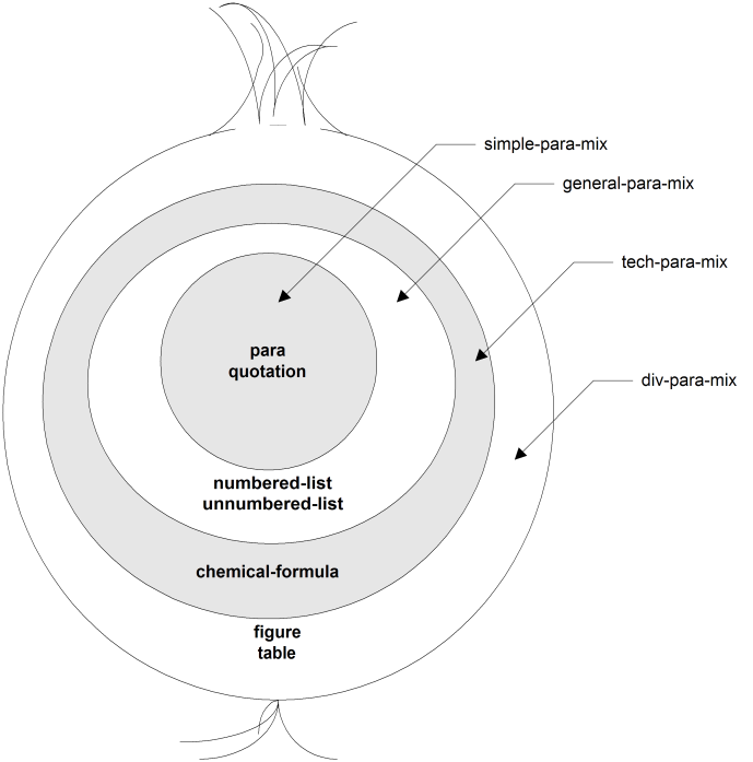
Using a traditional approach to constructing parameter entities that we call the “onion” approach, you would make successively larger collection entities that wrap around smaller ones, as shown in Figure 9.1, “Onion Approach to Collection Parameter Entities”. However, this approach creates unnecessary dependencies between entities and makes it difficult for DTD readers to follow what's going on.
Using the onion approach, you might or might not store the element classes in their own entities for convenience. The structure in Figure 9.1, “Onion Approach to Collection Parameter Entities” would correspond to entity declarations along the following lines, if you haven't used entities to hold each element class.
<!ENTITY % simple-para-mix  "para
                            |quotation">
<!ENTITY % general-para-mix "%simple-para-mix;
                            |numbered-list
                            |unnumbered-list">
<!ENTITY % tech-para-mix    "%general-para-mix;
                            |chemical-formula">
<!ENTITY % div-para-mix     "%tech-para-mix;
                            |figure
                            |table">
Alternatively, the declarations would look more like the following if you did use parameter entities for element classes.
element class entities:
<!ENTITY % textblocks      "para|quotation">
<!ENTITY % lists           "numlist|unnumlist">
<!ENTITY % chemical        "chemdiagram">
<!ENTITY % illustrations   "figure|table">
collection entities:
<!ENTITY % simple-para-mix  "%textblocks;">
<!ENTITY % general-para-mix "%simple-para-mix;|%lists;">
<!ENTITY % tech-para-mix    "%general-para-mix;|%chemical;">
<!ENTITY % div-para-mix     "%tech-para-mix;|%illustrations;">
Either way, you can't adjust the contents of any of the lower collections without affecting higher ones, and you force DTD readers to search through as many as four levels of complex entity contents to figure out what a division contains.
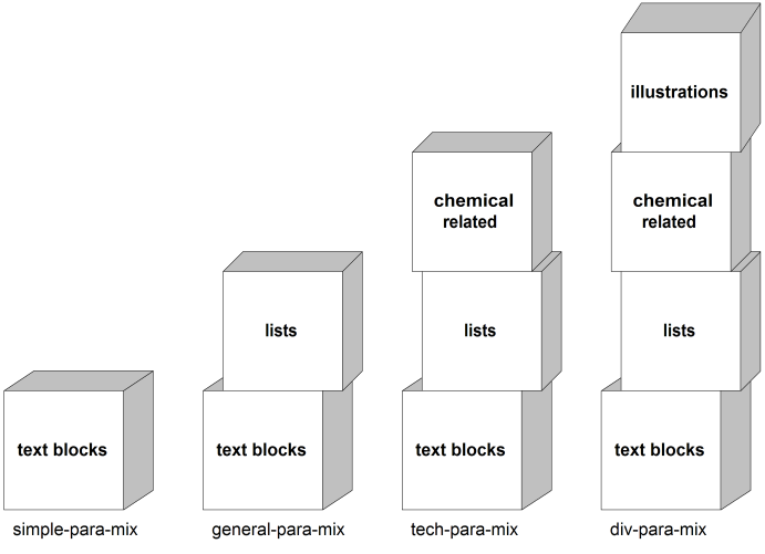
A “building block” approach, as illustrated by Figure 9.2, “Building Block Approach to Collection Parameter Entities”, is preferable. With this approach, you make entities for the element classes and use those entities as the basic raw material for the collection entities.
This scheme would look as follows.
element class entities:
<!ENTITY % textblocks       "para|quotation">
<!ENTITY % lists            "numlist|unnumlist">
<!ENTITY % chemical         "chemdiagram">
<!ENTITY % illustrations    "figure|table">
collection  entities:
<!ENTITY % simple-para-mix  "%textblocks;">
<!ENTITY % general-para-mix "%textblocks;|%lists;">
<!ENTITY % tech-para-mix    "%textblocks;|%lists;|%chemical;">
<!ENTITY % div-para-mix     "%textblocks;|%lists;|%chemical;|%illustrations;">
This scheme keeps the nesting of entities to two levels at a maximum. Also, even though four element class entities are mentioned in the largest collection entity, they are the only entities that DTD readers will ever need to refer to when looking up element contents, and the element class entities are largely self-documenting.
With this scheme, when you need to make adjustments to collections, you have pinpoint control: If a new text-block element such as note is added, you can simply edit the % textblocks; element class entity. If, as a result of testing the conversion of legacy documents, you discover that the contents of “simple” elements need to be broadened to include lists, you can simply edit %simple-para-mix; to add %lists;. Note that, even though the % simple-para-mix; and %general-para-mix ; might now have the same contents, the elements that refer to each one retain their autonomy; you can still modify one group independently of the other.
Further, the building block scheme facilitates the creation of collections that pick and choose more discriminatingly from the element classes at hand, rather than building solely on smaller collections. For example, what if, in addition to the four desired collections, you needed to add a new one as follows, which “skips” an element class?[14]
| text blocks | lists | chemical related displays | illustrations | |
|---|---|---|---|---|
| nontechnical division mixture | X | X | X |
The onion approach, even with element-class entities, would be at a disadvantage because the relationships of the different collections become more and more obscure. You need to branch out to two different “onions” after the innermost layer, %simple-para-mix ;.
<!ENTITY % simple-para-mix      "%textblocks;">
<!ENTITY % general-para-mix     "%simple-para-mix;|%lists;">
<!ENTITY % tech-para-mix        "%general-para-mix;|%chemical;">
<!ENTITY % div-para-mix         "%tech-para-mix;|%illustrations;">
<!ENTITY % nontech-div-para-mix "%general-para-mix;|%illustrations;">
On the other hand, you could make everything clear (and continue mimicking the matrix in the document analysis report, even to the point of leaving a “hole” in the declaration) with the building block approach.
<!ENTITY % simple-para-mix      "%textblocks;">
<!ENTITY % general-para-mix     "%textblocks;|%lists;">
<!ENTITY % tech-para-mix        "%textblocks;|%lists;|%chemical;">
<!ENTITY % div-para-mix         "%textblocks;|%lists;|%chemical;|%illustrations;">
<!ENTITY % nontech-div-para-mix "%textblocks;|%lists;           |%illustrations;">
Note that this “skipping” technique only disallows the chemical-related elements from appearing directly inside elements where the %nontech-div-para-mix; collection has been used. For collections at the data level, it's common to need to customize collections so that a particular element (or a whole class) is disallowed from appearing anywhere within itself.
Creating a huge set of slightly differing collections will be ineffective for this purpose, as well as causing a maintenance headache. A better solution is to use “regular” collection entities, but to put SGML exceptions on the individual element declarations involved. For example:
<!ENTITY % basic             "emphasis|partnumber|...">
⋮
<!ENTITY % general-data-mix   "%basic;|...">
⋮
<!ELEMENT emphasis - - (%general-data-mix;)* -(emphasis)>
Be careful of interactions between SGML exclusions and the granules in which your information will be created, stored, and reused. If the document hierarchy imposes global restrictions through SGML exclusions, but the information is created in nested “document” units at lower levels where there is no explicit restriction, assembly of whole documents will reveal invalid uses of restricted elements. It's safest to use exceptions only at low levels, preferably the data level, and just for the purpose discussed above.
The document analysis report may have indicated which elements should have the same content model or attribute characteristics, or you may find that you're repeatedly running across the same whole or fragmentary content model, or whole or fragmentary attribute declaration. In cases where the model should stay in synchronization across the DTD, use parameter entities or declaration name groups to stand for the repeated parts.
If multiple elements should, by design, have identical content (including all inclusion and exclusion exceptions), you might want touse a name group in place of a single generic identifier in the element declaration, as shown, to ensure the content models will stay in lockstep.
<!ELEMENT (numbered-list|unnumbered-list) - - (item+)>
Likewise, if multiple elements' attribute declarations should, by design, be identical, you might want to use a name group in the attribute declaration.
<!ATTLIST (note|caution)
        security        (open|confidential)     open
>
Often, the elements that need this treatment are members of the same class. If all members of an element class have identical content or attributes, and you have a parameter entity that records the class members, you can refer to the entity in the declaration.
<!ATTLIST (%admonitions;)
        security        (open|confidential)     open
>
However, don't join declarations that aren't designed specifically to stay in synchronization with each other, because using name groups (whether through parameter entities or not) for unrelated elements can make it harder to find the declaration you want when reading the DTD.
If you think you might be breaking up the joined declaration in the future, or if the declarations can be joined for either the elements or the attribute lists but not both, instead use parameter entities to stand for the specifics of the content model or attributes, and keep the declarations separate.
<!ENTITY % list.content    "item+">
<!ELEMENT numbered-list     - - (%list.content;)>
<!ELEMENT unnumbered-list   - - (%list.content;)>
<!ENTITY % secur.att
        "security      (open|confidential)     open">
<!ATTLIST note            %secur.att;>
<!ATTLIST caution         %secur.att;>
For parameter entities that provide some fraction of a content model, you'll need to decide where to put the group delimiters (parentheses) and occurrence indicators—outside or inside the entity definition. In general, leaving them off gives you flexibility in changing the entity's characteristics at the point of reference, and putting them in ensures that the entity contents are used consistently. For example, look at the following three options.
option 1:<
!ENTITY % list.content   "item">
option 2:
<!ENTITY % list.content   "item+">
option 3:
<!ENTITY % list.content   "(item+)">
Option 1 is best for class and collection entities. It ensures that item is the element used but lets you decide at each point of reference how many must be supplied.
Option 2 ensures that at least one item must be present wherever this entity is used, but allows you to specify other elements as part of the model group in a natural way.
Option 3 is usually the best choice for general content model fragments. It lets you use the entity as the entire content model for each list with no additional parentheses supplied, which can indicate your intent to disallow additions to the content model. (However, you still have the ability to use the third entity in building larger models just as you would with the second.)
For every attribute definition, you need to supply a declared value, which serves as a kind of “data type” declaration, and a default value. However, the keywords for declared and default values are far from self-documenting, and, unfortunately, even though attributes usually need more explanation than elements, attribute documentation usually gets short shrift.
You can use parameter entities to make customized “SGML keywords” that help communicate your design intent to readers of the DTD. Using parameter entities also gives you an easy way to update your DTD if you decide to change the underlying keyword. Following are some examples of user-defined keywords that you may find helpful.
Especially if you have chosen to use a declared value other than ID for your symbolic ID attributes (as discussed in Section 8.3.2, “Designing ID and ID Reference Attributes”), you might want to make your own keyword for ID values.
<!ENTITY % id       "CDATA">
⋮
<!ATTLIST document
        id      %id;    #REQUIRED
>
For attributes that have a yes-or-no (Boolean) value, you might have chosen to use the NUMBER declared value (as described in Section 8.3.1, “Designing Enumerated-Type Attributes”) and interpret zero values as no,
false, or off, and nonzero values as yes, true, or on. In this case, you could make your own keywords for both declared and default values.
<!ENTITY % yesorno   "NUMBER">
<!ENTITY % yes       "1">
<!ENTITY % no        "0">
⋮
<!ATTLIST document
        incatalog       %yesorno;       %yes;
>
In cases where you must use attributes to contain physical measurement information related to formatting the document, such as graphic heights and table cell widths, make keywords for the unit of measurement to be assumed by processing applications.
<!ENTITY % picas  "NUTOKEN">
⋮
<!ATTLIST figure
        figdepth        %picas;         #REQUIRED
>
Where you have specified a default value of #IMPLIED, the action that must be taken by processing applications isn't explicit. (This situation is discussed in Section 8.3.3, “Designing Attributes with Implied Values”.) Using special keywords for the different requirements can help make your processing expectations clear.
<!ENTITY % get-from-parent "#IMPLIED">
⋮
<!ELEMENT section          - - (title, para+)>
<!ATTLIST section
        approach        (leftbrain|rightbrain)   leftbrain
>
<!ELEMENT title            - - (#PCDATA)>
<!ELEMENT para             - - (#PCDATA)>
<!ATTLIST para
        approach        (leftbrain|rightbrain)   %get-from-parent;
>
[14] Needing to customize collections by removing one element class from them is actually a fairly common occurrence that results from ambiguity problems such as those discussed in Section 8.2.1, “Handling Specifications That Specify Ambiguous Content Models”.